DEVICE FOR INTERIOR ILLUMINATION
This is initial patent application from 1996 translated from Serbian to English. Serbian patent application slightly varies in its form from the USA one, but it still should be internationally valid one according International Patent Law. This patent issuing process lasted for 10 years despite the Serbian law act stating that this process should be accomplished within 18 months, the process started in 1996 soon after I had successfully accomplished my study of electrical engineering on Belgrade State University and it was finally finished in 2006 after series of legal actions against Serbian Patent Institute, when I had all compact bulbs in my hose making this patent pretty much obsolete. But, this innovation is still useful in medical and cosmetic applications. During this a decade long process, the patent application is expanded with mono-phase variant too. The patent was inspired by so called “white rooms” in submarines and mines, with only aim to raise the mood of the crew and all bulbs in those rooms were possessing fat filaments to keep them constantly white warm. It seems that the classical incandescent bulb with thin filament can be used for the same purpose with proper driver, also with significantly improved efficiency (from class F to class C) and durability (from 1000 hours to 3000 operating hours).
THE FIELD OF TECHNIQUES THE DEVICE IS PERTAINED ON
The invention belongs to area of the general electric illumination and it is about power supply of the conventional incandescent bulbs and minor modification of the incandescent bulbs to maximize filament light emission.
TECHNICAL PROBLEM
The invention resolves the problem of the illumination of the interior with white continual light with full spectrum with the classical incandescent bulb. During the illumination of the interior with the classical bulb supplied with AC current occurs spectrum deformation that diminishes efficiency. This spectrum deformation occurs due to the small thermal capacity of the filament whose own temperature follows supplied AC voltage on its ends. Thereby the irradiated spectrum has its maximum and minimum that spreads between infrared and white color during the cycle of the supplied AC current.
During the warming and cooling of the filament of the incandescent bulb emanates light that almost entirely matches the irradiation of the black body on the current temperature of filament but the average spectrum during the whole AC cycle does not match the spectrum of the black body irradiation. So, the spectrum of incandescent light is, in fact, medial spectrum of the incandescent bulb during the whole cycle of the AC driving voltage. Therefore these bulbs have yellowish light as the medial spectrum color and yet the light is vibrant too with frequency of 100Hz (120Hz) for the AC current of 50Hz (60Hz).
This yellowish light has insufficient frequency or whiteness to stimulate pineal gland causing melancholy and sleep disorders. If the light of bulbs would be closer to the sunlight then it will be healthy beneficial to psycho-physical condition of the persons exposed to such light and also their working efficiency.
This health problem is dominant during long winter cloudy periods without the Sun at all especially in Nordic countries where is applying the cure in white rooms with the bright white light therapy and the identical cure is applying to the submarine sailors when necessary. With this invention of mine the cure in white rooms will become unnecessary at all.
STATE OF TECHNIQUE
Till now the continual white light with the full spectrum for the interior illumination has been generating mainly on two ways: by halogens lamps and by optical filters. Halogen lamps have fat filament that with its own increased thermal capacity (due to increased fatness) provides necessary warmness during insufficient supply of low voltage interval of AC cycle. Due to the thickness of the filament they have low resistance so they have to be supplied with low voltage of 12V and high current.
Halogen bulbs are more expensive and they require additional transformer for conversion from 220V or 110V to 12V too, and an extra wiring for 12V.
Another way is based on modification of the spectrum by an optical filter that reduce red component of the light. The filter itself is usually realized by the bluish coloring of the bulb’s glass that additionally diminishes efficiency.
EXPOSURE OF THE INVENTION’S ESSENCE
Purpose of this invention is power supply of incandescent bulb with the DC voltage which should provide constant temperature of the filament and the color of light. Such application requires powerful and cheap rectifier with reduced voltage’s ripple, with gradually graduate of voltage during switching on to avoid stress in the filament and thus to prolong lifetime of the bulb itself. DC voltage should be obtained by three-phase rectifier because the ripple effect is significantly smaller than on mono-phase rectifier. The three-phase rectifier also contains significant DC component that does not exist at all on the mono-phase rectifier.
Thereby the device for the power supply is mainly made of the widespread available components till now frequently used for other applications.
BRIEF DESCRIPTION OF THE INVENTION
The invention is minutely described in three possible variants of device for the power-supply of classical incandescent bulbs with DC electrical energy, depicted on the figures 1, 2 and 3 for the first and the second variants of the device respectively.
DETAIL DESCRIPTION OF THE INVENTION
White light is obtained by driving incandescent bulb with DC current. Yellowish light of the incandescent bulbs is originated in AC current load. Due to frequent lighting on and off (100 time per second for 50Hz AC current) their filaments are frequently worming and cooling, therefore they shining with white light only fraction of time when the AC voltage is maximal, and in all other intervals their light is either yellowish or reddish.
Effective voltage on the bulb is:
(1)
Corollary, for mono-harmonic AC current effective voltage is:
(2)
Power is:
(3)
Relative gain of power for three-phase half-rectifier or full-rectifier in respect to mono-phase full-rectifier is given by coefficient k:
(4)
For mono-phase bulb is k = 1. For three-phase half-rectifier with every single diode conducing in interval of value for k is:
(5)
Average available power is 41% higher for three-phase full rectifier than for mono-phase full rectifier. Voltage on three-phase full rectifier is charted on fig. 8.
Frequency of the alternate component of rectified current is 150Hz and for 50% is higher then for mono-phase bulb. In this case minimal voltage is equal to halved maximal voltage. Three-phase full rectifier with every single diode conducing in interval value for k is:
(6)
The voltage is 82% higher than in case of mono-phase full rectifier. Voltage of three-phase half rectifier is depicted on fig. 7.
Frequency of the alternate component of the current is 300Hz and it 200% higher than in case of mono-phase bulb. The lowest voltage is:
(7)
The gain is slightly lower than showed because the filament in the bulb is not linear resistor, but its resistance depends on temperature. This case is described with the following formula:
(8)
Whereas with the aid of Wien law is derived:
(9)
Hence it is obtained:
(10)
1.34906976820358 < k < 1.37946740611400
n factor is parameter in the formula filament’s resistance:
(11)
1.34906976820358 < k < 1.37946740611400
Graph of the function k(α) (0 < α < 2) is depicted on fig. 5. Assessment of the spectral image improvement is obtained via following formula:
(12)
Parameter of whiteness improvement is defined as:
(13)
Whereas:
(14)
⇒
(15)
1.13542794308379 < kf = 1.15707992528663
For the device with three diodes (i.e. three-phase half rectification) light is whiter for 13% (theoretically between 13.5% and 15%)
For the device with six diodes (i.e. three-phase full rectification) following relations are defined:
(16)
Graph of function k(α) (0 ≤ α ≤ 2) is depicted on fig. 6. Factor of power advancement is settled between:
(17)
1.62251845389151 < k < 1.71003834767464
For the value of whiteness improvement factor is obtained:
(18)
1.19579233447064 < kf < 1.23069528900732
For device with 6 diodes light is better for at least 19.5% (theoretically between 19.5% and 23%)
Schematic for the three-phase half-rectifier device with capacitor and inductance for the protection of the filament is given on fig. 1. Schematic of the device with three transformers and full rectification is given on fig. 2. Transformers’ ratio should be , i.e. they should reduce voltage 1.73 times. Device on fig. 3 does not posses filter. Diode D1 is used for filament relaxation because according its spiral structure it may posses inductance and accumulated energy. Purpose of first inductance L1 is to protect capacitor during switching on of the device. Purpose of second inductance L2 is to protect bulb itself during switching on, i.e. to limit maximal current and to alleviate temperature equalization between filament and the saddle. Fist inductance L1 can be much smaller than second inductance L2. Purpose of diodes D1 and >D2 also D7 and D8 is to relax inductances L1 and L2 respectively during circuit switching off.
Dominant failure mechanism of tungsten filament is thermal fatigue appearing in hot filament and still cold filament’s saddle in the initial moments of bulb’s operation. By these all the lifespan of the bulb is significantly elongated.
Optimal values for the inductances are obtained from the condition that the device should not yield back reactive power into the electric grid:
(19)
Approximate formula for minimal voltage in respect to the capacitors (without inductance L2) is given by:
(20)
Except the improvement of the spectrum of the light the ripple of the light is also reduced that diminish eyes fatigue. The bulbs lust longer with significantly improved efficiency.
Device from fig. 3 is simplified variant of the device from fig. 1, where the diode D1 can be omitted in case of lower power bulbs, i.e. less than 150W. As the DC component is pretty high the filter can be omitted too with already defined improvement of the whiteness of bulb’s light.
The final price of the device can be reduced by usage of already available components: for inductance can be used neon tubes ballast and the capacitor for the washing machines can be used too. The optimal price is achieved when the device is used for supply of all ceiling bulbs by positioning device on the appropriate place in the electric installation of the room.
The device works instantly with obvious improvement of the whiteness of the light. The device is tolerant to the various values for the capacitors and the inductances in manner to work correctly within the entire range of the values for these components. This provides ability of usage cheaper components with greater tolerances.
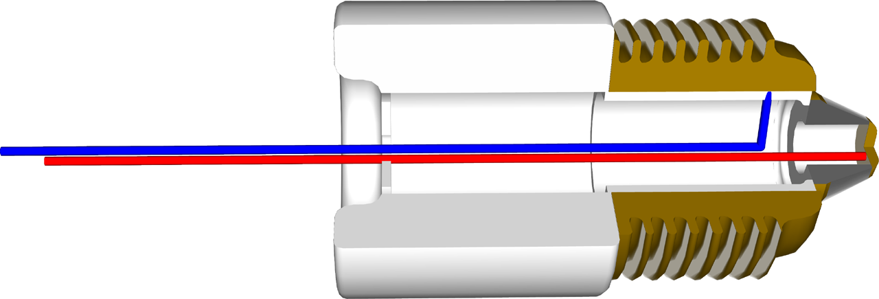
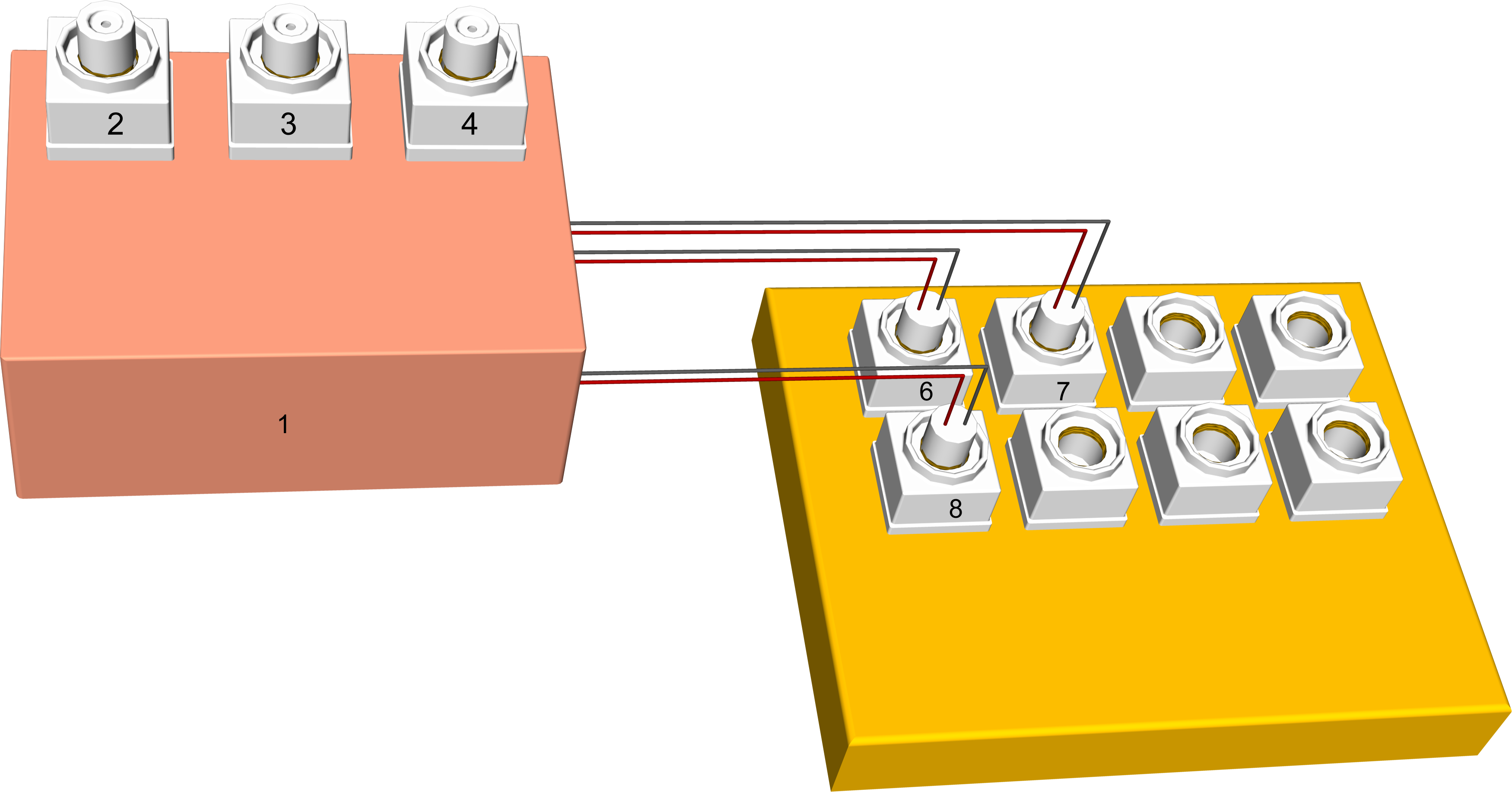
The device can be attached to the existing electric grid without drilling of walls via adapter on fig. 4 utilizing one wire from the fuses on different phases and then the voltage should be treated by the some of devices from fig. 1, 2 or 3 and then plugged in into illuminating part of the electric grid with the identical adapter into appropriate fuse of lighting as shown on fig. 9.
Realization show on
fig. 9 is consisted of a variant of the device settled in box 1 with fuse
sockets 2, 3, 4, attached to the electric grid on existing fuse box thus is
found lightening fuse 8 and two more fuses 6 and 7 on different phases than
fuse 8. Then fuse 8 is translated into fuse socket 2 in fuse
Dipl.-Ing. Andrija Radović
____________________
PATENT APPLICATION
THE DEVICE FOR INTERIOR ILLUMINATION, denoted that it is consisted of diodes (DR, DS and DT) from which every single one is with its one end attached to one of three supplying phases R, S and T respectively and its another end attached to the mutual spot (1), inductance (L1) attached with its one end to the spot (1) and with another one to the spot (3), inductance (L2) attached with its one end to the spot (3) and with another one to the spot (4), diode (D1) attached with its ends to the spots (3, 4), incandescent bulb and filament ends attached to the spots (2, 4), all according fig. 1.
THE DEVICE according application 1 in variant II, denoted that it is consisted from transformers (T1, T2, T3) connected to the supplying phases R, S and T attached to the spots (1, 2, 3), secondary side of the transformers are attached to the spots (4, 5, 6), diodes (D1 to D6) attached to the secondary windings of the transformers to the spots (4, 5 ,6) and with their another ends attached to the spots (7, 8), inductance (L1) with its ends attached to the spots (7, 8) and inductance (L2) attached to the spots (9, 10), capacitance (C) attached to the spots (7, 9), two diodes (D7, D8) that relaxes inductances (L1, L2) on disconnecting, all according fig. 2.
THE DEVICE according application 1 in variant III, denoted that it is consisted from diodes (DR, DS and DT) attached with their mutual ends to the spot (1), and with their another ends connected with the supplying phases R, S and T, diode (D1) attached in spots (1, 2), and incandescent bulb attached to the electric circuit in spots (1,2), all according fig. 3.
ABSTRACT
DEVICE FOR INTERIOR ILLUMINATION
This device provides illumination with full spectrum white light achieved by DC supply instead of increase of thermal capacity of the filament of the bulb. Therefore standard incandescent bulbs are used.
The device is relatively cheap and it can be incorporated into existing residential electric grid with minor adaptations.
This invention supplies bulbs with DC voltage that should provide constant temperature of the filament and therefore full spectrum too. Such applications require powerful and cheap rectifier with minimal ripple, which will gradually increase voltage on the bulb during switching on moments to avoid stress in the filament and to elongate lifespan of the bulb.
DC voltage is obtained by three-phase rectification because ripple is lesser than in case of mono-phase rectification. Three phase rectifier contain significant DC component that does not exist in case of mono-phase rectifier.
Therefore supplying device is made mainly of widely available components till now used for other purposes.
Dipl.-Ing. Andrija Radović
____________________
Fig. 1
Fig. 2
Fig. 3
Fig. 4
Fig. 5
Fig. 7
Fig. 8
Fig. 9
Dipl.-Ing. Andrija Radović
____________________
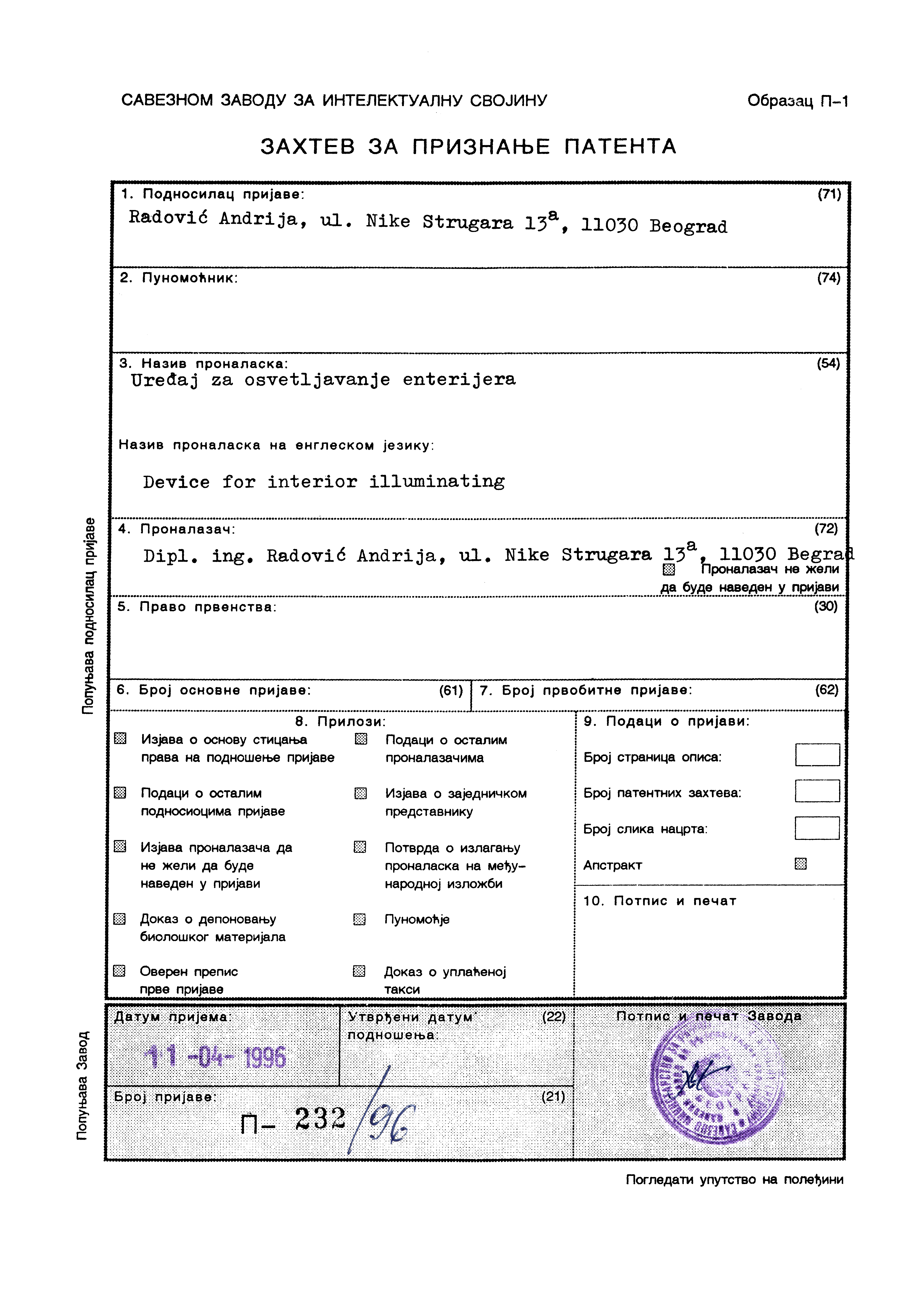
Patent receipt in Serbian confirming that patent documentation was submitted and that Patent Certificate issuing process is committed:
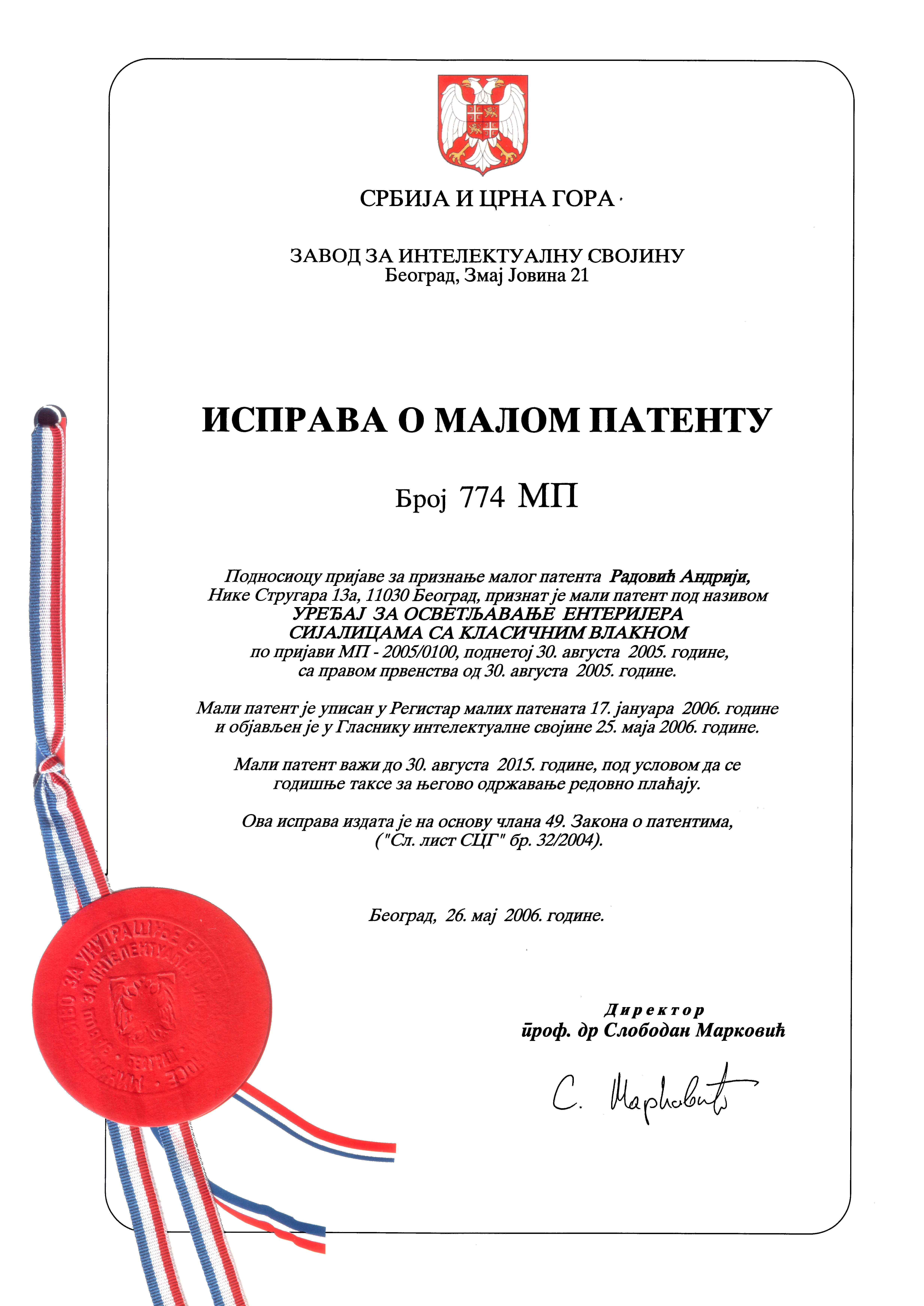
Patent Certificate in Serbian:
Owner of the patent
Dipl.El.-Ing. Andrija Radović
E-mails: andrijar@gmail.com, andrijaradovic@hotmail.com or andrijar@andrijar.com
Phone: +381 64 1404075